Cleaning and maintenance
- 1
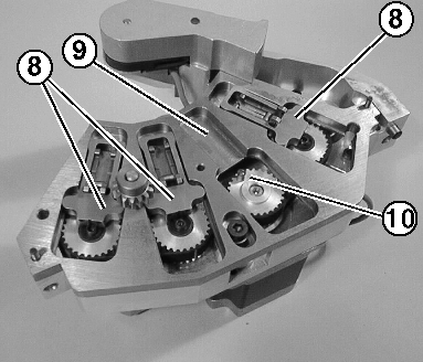
- Remove the connecting rod slide (8) from the guide plate (9).
- 2
- Remove the crank journal sleeves (10).
- 3
- Blow out the crankcase (1).
- 4
- Blow out the connecting rod slide (8) and check the rockers for smooth movement.
- 5
- Blow out the guide plate for the connecting rod slide (8).
- 6
- Lightly oil the slideways (9) for the connecting rod slide (8).
- 7
- Oil the crank journal sleeves (10) lightly and place them on the pins of the toothed washers.
- 8
- Insert the connecting rod slide (8) into the guide plate while making sure that the cross groove of the connecting rod slide is positioned on the crank journal sleeves (10) of the toothed washer.
- 9
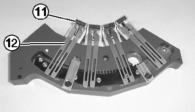
- Always blow and brush out the clamping and cutting needles (12), but do not remove if possible.
- 10
- Always blow or brush out the clamping pinion (11).
- 11
- Blow out the selector housing (3).
- 12
- Lightly oil the slideways of the clamping and cutting needles.
- 13
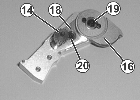
- Blow out the finger supports (2) and intermediate shaft (14).
- 14
- Remove the thread residues from the intermediate shaft (14) and the gearwheel of the transport segment (16).
- 15
- Remove housing (18), for this, remove screws (19) and (20).
- 16
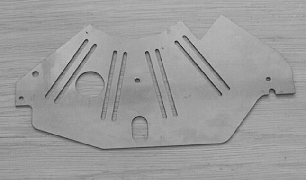
- Clean the intermediate plate thoroughly (4).
Install thread clamping and cutting device:
- 1
- Lightly oil the front and rear of the intermediate plate (4).
- 2
- Screw the intermediate plate (4) onto the crankcase (1).
- 3
- Position the finger support (2).
- 4
- Position the selector housing (3) on the crankcase (1) over the two setting pins. When doing so, the sensor cable must be laid into the recess on the crankcase (1) between the blade holder and the finger support (2).
- 5
- Screw on both cases with the screws (5) tight.
- 6
- Only slightly tighten (0.5 Nm) the sensor with the screw (6).
- 7
- Screw the finger support (2) and the securing clips of the sensor cable in tight with the screws (7). In the process the sensor cable must be strain-relieved from the securing clip to the sensor.