Putting up knitting machine
Lift the knitting machine with a ground conveyor (e.g. fork lift) and transport it.
In this case the following things have to be taken care of:
- The position of the centre of gravity is indicated on the front crosshead (carriage in left transport position).
- Both the lifting arms of the ground conveyor should be long enough so that the front and the rear crosshead can be lifted.
- Lift and set the machine carefully. Danger of damage if it hits the floor very hard.
Lift the machine only on both the machine feet or on the crossheads.
Setting up knitting machine:
- 1
- Remove the screwing of the knitting machine to the transport base.
DANGER

Heavy knitting machine!
Danger of injury for persons and damage of the knitting machine.
- Country-specific regulations for the prevention of industrial accidents for the transport of heavy loads are to be observed.
- Use only appropriate means of transport with sufficient load capacity for transporting and installing the knitting machine (e.g. fork lift).
- The relevant country-specific laws and regulations are to be observed when transporting with a ground conveyor (e.g. fork lift).
- Ground conveyor: observe the safety instructions of the manufacturer.
- Transport the machine always with the utmost caution and care.
- All transport locks are to be attached to the machine.
- 2
- Lift the knitting machine with a fork lift from the transport surface.
- 3
- Bring the knitting machine to the site of installation.
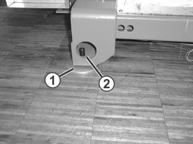
- 4
- Lay Washers (1) from the accessories under the knitting machine foot. Place the washers in such a manner that the cavity comes exactly under the grub screw (2).
- 5
- Setting knitting machine on the floor
- 6
- Remove wood pieces, adhesive strips, packing film and paper.
- 7
- Remove the screws (5). In the case of the CMS 502, loosen the screws (5).
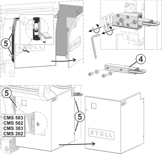
- 8
- Swivel the cover of the control unit outwards. In the case of the CMS 502, remove the cover.
- 9
- Remove the transport flap (4).
In the case of the CMS 502, the steps 10 to 13 are not necessary.
- 10
- Remove the safety nut (6). It does not move easily since the safety nut is self-locking.
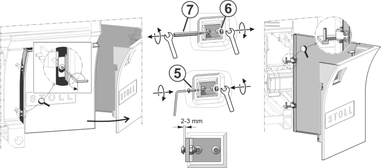
- 11
- Unscrew the distance bolt (7).
- 12
- Screw the screw (5) into the holder until it protrudes at the rear of the holder and the safety nut can completely be screwed-on.
- 13
- Hook-in the control unit cover in the rear position.
- 14
- Close the cover. Ensure that the cover engages in the screws (5).
- 15
- Tighten the screws (5); this way the cover is secured.
- 16
- Repeat the steps 7 to 15 on the other machine side.
- 17
- Remove all transport locks.

|
|
Transport lock for: | ||
|
1 |
Carriages |
5 |
Cover at comb take-down |
|
2 |
Touch screen |
6 |
Comb take-down |
|
3 |
Drive |
7 |
Comb take-down (2 pieces for CMS 7xx and CMS 8xx) |
|
4 |
Left and right cover |
|
|
Preserve the transport locks.