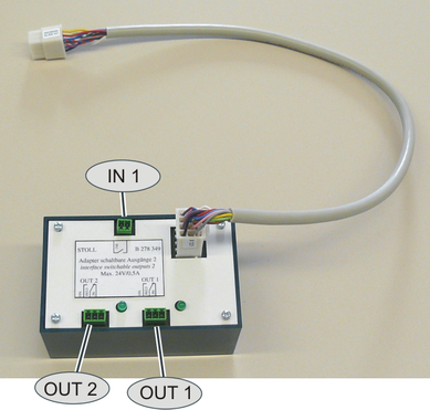
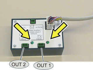
Adapter for Switchable Outputs 2 (ID 278 349)
|
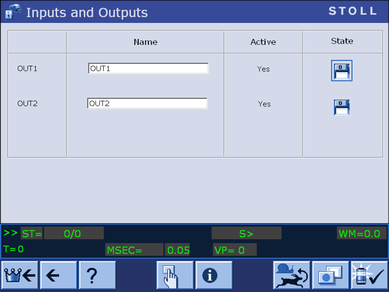
OUT1 OUT2 |
Two potential-free relay outputs which enable external devices to be switched on and off (a maximum of 24V/0.5A) are available. |
|
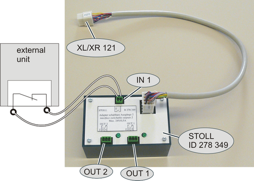
IN1 |
An input is available to which a potential-free switch NC or NO contact can be connected. |
The devices are switched on or off by the knitting program.
|
Command |
|
|
OUT1=n |
Switch on/off device 1 (on: n=1, off: n=0) |
|
OUT2=n |
Switch on/off device 2 (on: n=1, off: n=0) |
|
IN1 |
Specify the behavior of the machine |
Assembly
- 1
- Switch off main switch.
- 2
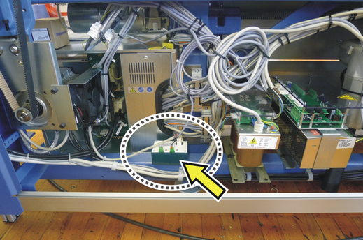
- Open the rear panel segments.
- 3
- Plug the adapter to the control unit.
- 4
- Plug-in the cable for "OUT1", "OUT2" and "IN1" to the adapter.
- 5
- Close the rear panel segments and switch-on the main switch.
- 6
- If you don't use the "IN1" input, execute a "Warmstart".
- 7
- If you want to use the "IN1" input, execute a "Restart & Configuration".
|
EKC machine |
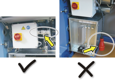
Plug-in "XL/XR 121" plug into the "X 121" socket of the right control unit |
|
OKC machine |
Plug in the "XL/XR 121" plug into the "X 121" socket of the left or right control unit (depending on machine type) |
Use
- You can use the "OUT1" and "OUT2" outputs with the OKC and EKC machines.
- You can use the "IN1" input only with machines with single-phase power supply. This depends on the type of computer of the knitting machine.
|
|
Computer Type |
|---|---|
|
OUT1 |
EKC2 |
|
IN1 |
EKC2
|
|
* Machine with single-phase power supply
|
Activate the display of "IN1".
 Konfiguracja maszyny ->
  Ustawienia operacyjne ->
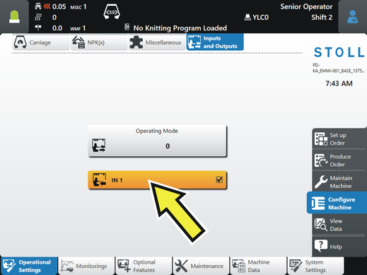
If the input is activated, the following points are possible:
- The "IN1" input can be checked without a knitting program (see section "LED on the adapter").
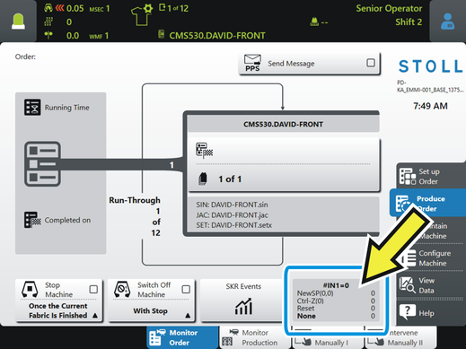
- During production, the status of IN1 is displayed.
LED on the adapter
If the or command is executed by the knitting program, the corresponding LED lights up on the adapter.
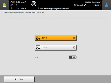
Manual check of the LED:
|
EKC machine |
Activate "OUT1" – LED for "OUT1" lights up Activate "OUT2" – LED for "OUT2" lights up
"IN1"
"IN1" |


 - External signal "0" is present
 - External signal "1" is present
|
OKC machine |
Machine settings -> additional function keys -> Switchable outputs
Activate "OUT1" (switch on "1") – LED for "OUT1" lights up Activate "OUT2" (switch on "1") – LED for "OUT2" lights up |
 ->
->  ->
-> 
Przykład na użycie wejścia "IN1"
Przędza elastyczna ma być monitorowana pod kątem węzłów. Do monitorowania przędzy elastycznej wykorzystywany jest dodatkowy, zewnętrzny detektor węzłów.
Węzeł pojawia się na przykład podczas zmiany nawoju. Węzeł prowadzi do wady jakościowej, dzianina jest bezużyteczna. Dzianina nie musi być ukończona i będzie automatycznie ponownie wystartowana.
Użyj nowego adaptera i zakończ program dziania tak aby maszyna szybko ukończyła wadliwy element dzianiny i rozpoczęła nowy.
- Węzeł został wykryty
- Węzeł został wdziany
Określ liczbę rządków dziania w programie dziania. - Produkcja dzianiny zostanie przerwana
W programie dziania określasz działanie maszyny. - Nowa dzianina zostanie rozpoczęta.
W programie dziania określasz, jak maszyna powinna działać:
CTRLZ(x) | Maszyna rozpocznie automatycznie dzianie nowego elementu jeśli następujące warunki są spełnione:
x = liczba rządków do wykonania działania |
NEWSP(x,y) | Anuluj aktualną dzianinę i zacznij od nowa. x = liczba rządków do wykonania działania y = numer linii, od której chcesz startować program dziania |
Przykład z "CTRLZ":
30 START | Linia 35 - aktywuj automatycznie CTRLZ za pomocą #IN1 Linia 70 - jeśli zostanie wykryty węzeł, komenda "CTRLZ" jest wykonywana po 6 rządkach.
Linia 200 - monitorowanie węzłów będzie aktywne w dodatkowym obszarze w programie dziania. Linia 400 - wyłączenie #IN1 |
 Jeśli pracujesz z "NEWSP", zastąp powyżej wymienione specyfikacje dla "CTRLZ(x)" z "NEWSP(x,y)".